PEDIATRIC KNEE-DOWN PROSTHETIC
A Cost-Effective Adjustable Solution.
Knee-down pediatric prosthetics currently lack adjustability for different age groups. Due to the growth rate of children, parents have to purchase new prosthetics every 6 months, posing a financial challenge for families. Our solution is a cost-effective prosthetic that can have it’s length, diameter and suspension of the limb easily adjusted, while offering a secure and comfortable prosthetic that avoids irritation when in contact with the upper leg.

MODELS AND DRAWINGS


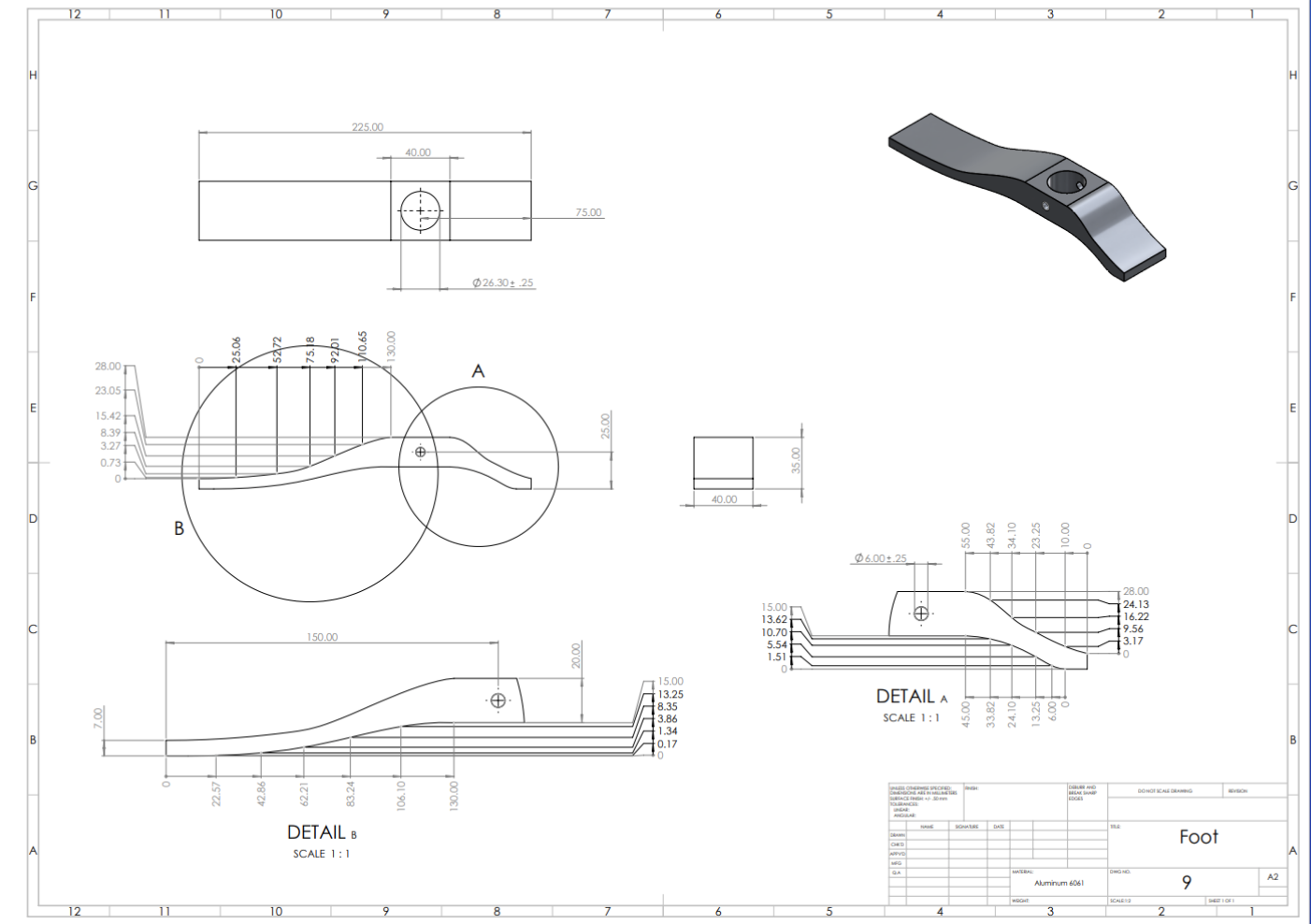
Foot Drawing

Shock Absorption Piece Drawing

Telescoping Leg Drawing

Full Assembly Drawing
SIMULATIONS
DIAMETER

FORCE v. TIME
TOLERANCE STACK UP ANALYSIS
Tolerance stack-up was analyzed on 3 fitted parts: the shock absorber piece, the bottom leg, and the top leg, for both the height and the diameter of the system of the fitted pieces. The simulation results show very tight tolerances. This is good because it means pieces will be well fitted, providing the stability necessary for the product, however, tight tolerances allow less space for tolerance error when machining the pieces. This could cause galling of the material over time, making the prosthetic lock up. Additionally, a tighter tolerance means the cost will rise exponentially. A method to reduce the costs is to add gaps in the CAD model to compensate for the tolerance deviations.


MOTION ANALYSIS
FEA ANALYSIS
STRESS, DEFORMATION AND STRAIN

HEIGHT

The FEA simulation models a full load of a child running at maximum speed. The impact force was calculated to be 6900 N, after multiplying a maximum weight of 130Ib by a safety factor of 3, and a factor of 4 due to the force created when running at max speed. This force was applied to the top of the assembly. The fixed roller position is the foot when in contact with the ground, allowing the foot to move left and right, but not up and down.
The results show that the only parts that fail due to the stress or strain at FOS of 3 are the areas around the hole. This is expected as hand calculations were done prior to modeling using the assumption that it is a cylinder with no features. Doing additional calculations accounting for the hole will solve this problem. Nevertheless, values of failure are within bounds at a FOS of 2.25, proving it is a structurally effective model.
FACTOR OF SAFETY 2.25 AND 3

The analysis consists on a linear motor attached to the top of the assembly, simulating a standard force and acceleration of a person’s body on the prosthetic. The spring reacts to the motor displacement, causing a reaction force in the motor(person) as it has to output more energy to overcome the spring force. The results shows that a 7000 Newton force is required to displace the leg by 3mm. This was the calculated and expected value, as the spring was designed so that the entire force of a standing body will be absorbed by the spring, creating a shock absorption system.

SPRING SYSTEM

CAM ANALYSIS
A CAM simulation is made to assess crashing and accuracy when manufacturing while generating a toolpath. The CAM code for the shock absorber piece was completed with Fusion 360. The stock piece was first oriented so the flat pieces were in the y axis. From there, a 7 mm shaft diameter was used to cut the correct size of stock. After that, a 3 mm shaft diameter was used to cut the top pocket, followed by a 6 mm shaft to shape the bottom, hollow it out, and finally cut out all the through-holes necessary for the piece.